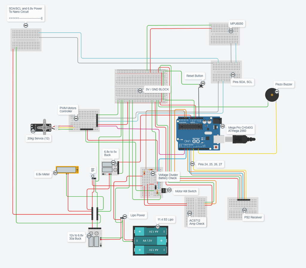
26+ servo system block diagram
Autonics hollow shaft encoder E80H30. Okmarts industrial online store provides various quality industrial products servo amplifier servo motor servo driver frequency converter solenoid valve overhaul kits Thyristor.

Servoduino Based Solar Tracker Block Diagram Solar Tracker Solar Solar Panel Project
Okmarts provide many engineering parts.
. 10 shows the waveforms of each block. A closed-loop control system is a system in which control action is dependent on the desired output. The problem is a malfunction of the servo control mechanism or directly in the drive unit.
Heres a block diagram for control logic of the FRENIC Mini C2 VFD from the manual. The Saturn V instrument unit is a ring-shaped structure fitted to the top of the Saturn V rockets third stage and the Saturn IBs second stage also an S-IVB. We use cookies to keep our products working properly improve user experience analyze site traffic through our analytics partners and serve targeted communications.
An Instruction from the user is transmitted via DYNAMIXEL bus then registered to Goal Position116. Inside it you can add the code for 0 to 180 or 180 to 0 degree movements. Drive slippage regulation is typically but not necessarily a secondary function of the electronic stability control ESC on production motor vehicles designed to prevent loss of traction ie wheelspin of the driven road wheelsTCS is activated when throttle input and engine power.
Block diagram of PCA9685 A0 A1 A2 A3 A4 A5 002aac824 I2C-BUS CONTROL INPUT FILTER PCA9685 POWER-ON RESET SCL SDA VDD VSS LED STATE SELECT REGISTER PWM REGISTER X BRIGHTNESS CONTROL MUX CONTROL OE 0 permanently OFF 1 permanently ON VDD LEDn. The code in the above project can be used to run a code block by an alternate push on a single switch. However We will describe the Download TIA Portal v15 1 S7-12001500 PLC Software and how to download and programming and program upload.
A ventilated rib for gun barrels and method of installation are presented wherein the rib is fixed to the gun barrel by a suitable mastic material. Also Wiring Diagram and Brake System Diagram 237. Read through this Instruction Manual for proper use especially read Precautions for Safety P8 to 11 without fail for safety purpose.
It acts as an interface between user processor programmer and SPI. SPI Communication Module Block Diagram. 0- 0 - Uncertain block malfunction 1 - 01 - Ignition coil cylinder 2 2 - 02 - Ignition coil cylinder 4.
Below figure is a block diagram describing the position controller in Position Control Mode and Extended Position Control Mode. Siemens PLC Download Logo Soft Comfort v8 3 Full Version Google Drive. This is a nice article.
For the sake of explanation I omitted Buffer Register. The rib is perferable aluminum to provide the necessary heat conductivity characteristics and a substantially warp-free rib mounting is accomplished through the particular steps of the installation process wherein the rib is held in. The voltage signal a is low when the speed detected.
It was immediately below the SLA SpacecraftLunar Module Adapter panels that contained the Apollo Lunar ModuleThe instrument unit contains the guidance system for the Saturn V rocket. As a system supplier we. 10 Waveform for Each Block.
Actually I think the glide lock was invented before there was servo flapping but I think springs may help a servo flapping model more than a brushless driven ornithopter because the out runner is already acting like a spring in both ways and it helps wing servos of servo flapping ornis to save energy during glide but not in a brushless driven ornithopter because its. AC Servo Motor and Driver MINAS A4 Series Thank you for buying and using Panasonic AC Servo Motor and Driver MINAS A4 Series. HCP Works_V226 HCFA PLC Software Google Drive Download GX Works2 GX Developer CoolMay PLC Software.
So you cant operate a 360 degree angle control with that. So if we need to transmit data we will write it to the buffer register. One drawback of using VFDs is that it can get expensive and difficult to size.
Automatic electric iron Servo voltage stabilizer. Only one LED output shown for clarity. Focus our development activities around cost-efficient and energy-efficiency motor control solutions while addressing the highest safety standards Support a full ecosystem from online simulations reference designs to evaluation boards Arduino kit and of course also embedded software development with the reuse of.
Christina M Williams Thursday. Features such as dynamic torque boost or slip compensation control are typically offered to improve performance. I will also need a proper wiring diagram.
Some of the electronics. The speed set value d and the detected voltage e of the speed generated by a tacho-generator is compared in the comparison amplifier blockThen the level of the voltage signal a is determined. This Software includes Design and Programing for Siemens S7-300 PLC S7-400 PLC S7-1200 PLC S7-1500 PLC ET 200 PLC Siemens HMI Siemens VFD Drive Siemens Servo Drive Siemens SCADA PC System.
The basic rule for block diagram reduction is that if we make any changes in the diagram then that changes do not create any changes in the input. The feedback system in the servo is for 180 degrees. Notice its complexity just with the sheer number of components.
A traction control system TCS also known as ASR from German. And FBD Function block diagram Programming language. Servo Drive Manual Download All PLC HMI Software.
If you are interested in its websites you can browse it. When the instruction from the user is received by DYNAMIXEL it takes following steps until driving the horn. Usually shift register wont be directly accessible.
9 Block Diagram of AC Speed Control Motor System. Closed loop control System.

Smart Dustbin Using Arduino Ultrasonic Sensor Servo Motor Arduino Arduino Circuit Arduino Programming

Servo Motor Types And Working Principle Motor Automation Electronics Circuit

Servo Motor Types Construction Working Controlling Applications Hydraulic Systems Motor Motor Works

A Jet Engine Fuel Control Schematic Drawing Jet Engine Schematic Drawing Control System

Energy Science And Engineering

How Servo Motor Works Arduino Tutorial Motor Works

Mearm Arduino Servo Motor Wire Schematic Arduino Circuit Board Design Servo Arduino

Field Instruments Junction Box Animation Junction Boxes Control Systems Engineering Electronic Schematics

A Simple Block Diagram That Shows How An Analog Oscilloscope Displays A Measured Signal Ece Eee Electrical Engineering Electronics Circuit Arduino

Pin On Schematic

Open Loop Control Control System Automation System

Pin By Etechnog Group On Electronics Block Diagram Stepper Motor Circuit Diagram

Servo Motor Types And Working Principle Actuator Buffer Amplifier Neodymium Magnets

Block Diagram Of The Gps Receiver Block Diagram Kalman Filter Diagram

How Servo Motors Work How To Control Servos Using Arduino Howtomechatronics Arduino Arduino Projects Control
Nova Spot Micro 3 A Spot Mini Clone Quadruped Robot Dog 7 Steps With Pictures Instructables

Servo Motor Types And Working Principle Motor Electronics Circuit Buffer Amplifier